
Logic Hydraulic Cylinder Designer 2D
Win64, EnglishGeneral Usage Instructions
Check the documentation for the detailed tutorial.
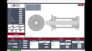
- The user enters push, pull force, pressure, stroke, bolt quality, safety factor, and speed in the left panel. Then, the User selects the connection type and operation type in the left panel. Finally presses the calculate button. It outputs to the interface as 2D in the right panel.
For details see: Lesson1- Building a Basic Hydraulic Cylinder
- After this stage, the user can add, remove or change new features. The tube metric thread and outer diameter can be changed that the given range from the panel of the tube features. The rod metric thread and stroke can be changed that the given range from the panel of the rod features. The back cap outer diameter and bolt can be changed that the given range from the panel of the back cap diameter features. If the clevis is active in the connection type, you can change the clevis type and set the center distance.
For details see: Lesson2- Tube, Rod, and Back Cap Properties
- The head cap diameter can be changed that the given range from the panel of the head cap features. Users can change the head cap seals by double-clicking on the head cap in the 2D panel.
For details see: Lesson3- Head Cap Properties
- The piston metric thread can be changed that the given range from the panel of the piston features. Users can change the piston seals by double-clicking on the piston in the 2D panel.
For details see: Lesson4- Piston Properties
- If the round flange at base properties is selected from the connection type, properties such as diameter and bolt can be changed on the panel opened by double-clicking the round flange at base.
For details see: Lesson5- Round Flange at Base Properties
- If the round flange at head properties is selected from the connection type, properties such as diameter and bolt can be changed on the panel opened by double-clicking the round flange at the head.
For details see: Lesson6- Round Flange at Head Properties
- For technical drawing edits, click on the technical drawing button. Title block information is edited. The parts to be output is selected.
For details see: Lesson7- Export to Technical Drawing
Screenshots


Commands
Installation/Uninstallation
Installation:
Download and run Logic Hydraulic Cylinder Designer 2D.exe.Choose your destination folder and follow the onscreen instructions to install the software.
After installing the program, you'll need a license key to log in to the program. For this, go to logicps.net/plans-pricing, choose the Free package from the payment plans and sign up. A license key will be sent by Logicps to the email address that you used when signing up.
You can log in to the program with this e-mail address and license key. If you do not receive the email with your license key please contact Logicps at info@logicps.net.
NOTE: An internet connection is required in order to install/utilize the plugin as our libraries are all cloud-based.
Uninstallation:
To uninstall this program, click Control Panel > Programs > Programs and Features, and uninstall it as you would any other application from your system.
Additional Information
Known Issues
Contact
Author/Company Information
Support Information
Email: info@logicpc.net
Version History
| Version Number | Version Description |
|---|---|
|
1.2.2 |
Added 2024 support |
|
1.2.1 |
Initial release. |
